


The physical layer, bits, signals, and transmission media are the core concepts of this lesson, which focuses on the lowest level of the network stack and data transmission via a physical medium.
The text explains that at the physical layer, data is no longer treated as packets or frames, but rather as sequences of 0s and 1s to be converted into transmissible signals.
The lesson outlines the main transmission media: electrical (such as copper cables), optical (such as fiber optics), and wireless (based on electromagnetic waves). It also explains the difference between analog and digital signals, using NRZ encoding as an example.
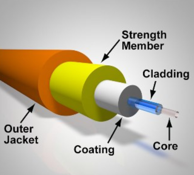
The final section examines fiber optics in greater detail, describing its structure—core, cladding, coating, strength member, and outer jacket—and the principle of total internal reflection, which allows light to remain guided within the fiber’s core, even over long distances.
Physical level
The physical layer is the lowest layer of the network stack. It handles the transmission of bits through a physical medium, such as a copper cable, an optical fiber, or the space through which radio waves propagate (International Organization for Standardization [ISO], 1994; Institute of Electrical and Electronics Engineers [IEEE], 2022).
At this layer, data is no longer considered as packets or frames, but as sequences of bits to be represented by physical signals. The task of the physical layer is therefore to convert 0s and 1s into signals that can travel through the transmission medium and then be correctly interpreted by the receiver (ISO, 1994; IEEE, 2022).
The transmission media used to create a channel in a network are usually divided into three categories, depending on the physical phenomenon used to transmit the bits:
The physical layer must encode data so that it can be carried by the transmission medium (IEEE, 2022, 2025).
The encoding method depends on the characteristics of the transmission medium being used: for example, to transmit information over a copper wire, a physical variable such as voltage or current is modulated (IEEE, 2022).
For this reason, there must be a network device that converts bits into signals suitable for the medium being used. This conversion can be performed by different components, such as an Ethernet network interface card, a Wi-Fi module, a modem, or an optical converter (IEEE, 2022, 2025; ITU, 2024a).
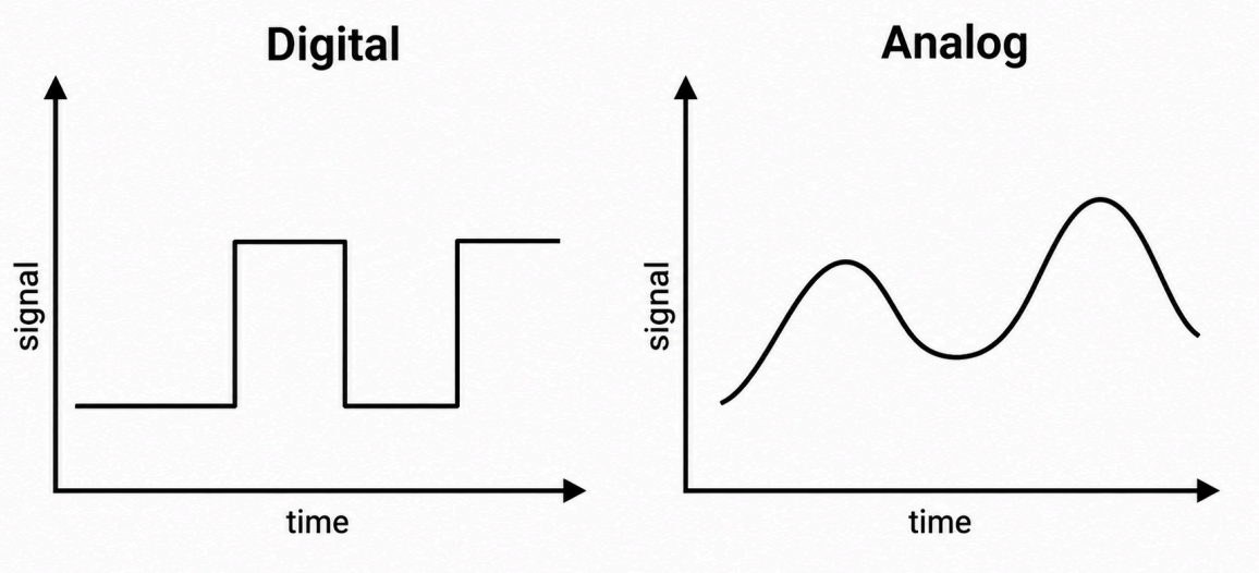
The signal transmitted through the medium can be of two types:
The type of signal depends on the medium and the technology: some encoding schemes transmit bits as a digital signal, using distinct voltage or light levels; in other cases, such as a modem on a telephone line, the bits are converted into an analog signal (the modem takes its name from this process of modulation and demodulation) (ITU, 1993; IEEE, 2022).
Example
A common example of encoding bits using a voltage signal is NRZ (Non-Return-to-Zero) encoding. In this encoding, each binary value is associated with a fixed voltage level, maintained for the entire duration of the bit:
Suppose we want to transmit the bit sequence “101010”.
With NRZ encoding, the voltage signal takes the following values in sequence:
+5 V, 0 V, +5 V, 0 V, +5 V, 0 V.
Note: this is a simplified example. In real technologies, such as Ethernet or Wi-Fi, physical-layer encoding schemes are much more complex.
Optical fiber
Optical fiber is a data transmission technology that uses light pulses to send information through a cable made of glass or plastic fibers (ITU, 2024a).
It is one of the most important and high-performance transmission media in modern networks, thanks to its high speed, large data-carrying capacity, and resistance to electromagnetic interference (ITU, 2024a; IEEE, 2022).
In simplified terms, we can imagine digital data being represented as follows:
In real technologies, however, light encoding and modulation systems can be more complex (IEEE, 2022).
Because the optical fiber itself is very thin and delicate, a fiber-optic cable is made up of several protective layers; specifically, its structure is as follows (International Electrotechnical Commission [IEC], 2023):
How does it work?
An optical fiber is an extremely thin strand (thinner than a human hair) capable of guiding light inside it thanks to a physical principle called total internal reflection (Ling et al., 2016; ITU, 2024b).
Total internal reflection causes a light ray, when it strikes the interface between the core and the cladding at a sufficiently large angle, not to exit but to be completely reflected (Ling et al., 2016).
Total internal reflection works because the core and the cladding have different refractive indices (Ling et al., 2016; ITU, 2024b).
The refractive index indicates how much light slows down when it passes through a material: the higher the index, the more the light is slowed (Ling et al., 2016).
In an optical fiber, the core has a higher refractive index than the cladding (Ling et al., 2016; ITU, 2024b).
When light travels through the core and reaches the boundary with the cladding, it tends to change direction.
Because it is passing from a material with a higher refractive index to one with a lower refractive index, the light bends away from the perpendicular to the boundary between the two materials (Ling et al., 2016).
If the angle at which the light strikes the boundary is large enough, the light would enter the cladding in a direction almost parallel to the boundary. Beyond a certain angle, called the critical angle, there is no longer a possible direction in which the light can propagate through the cladding. For this reason, the light does not leave the core but is completely reflected back inside it (Ling et al., 2016).
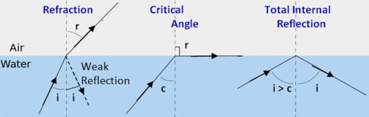
In this way, the light pulses remain guided inside the fiber and can travel long distances (Ling et al., 2016).
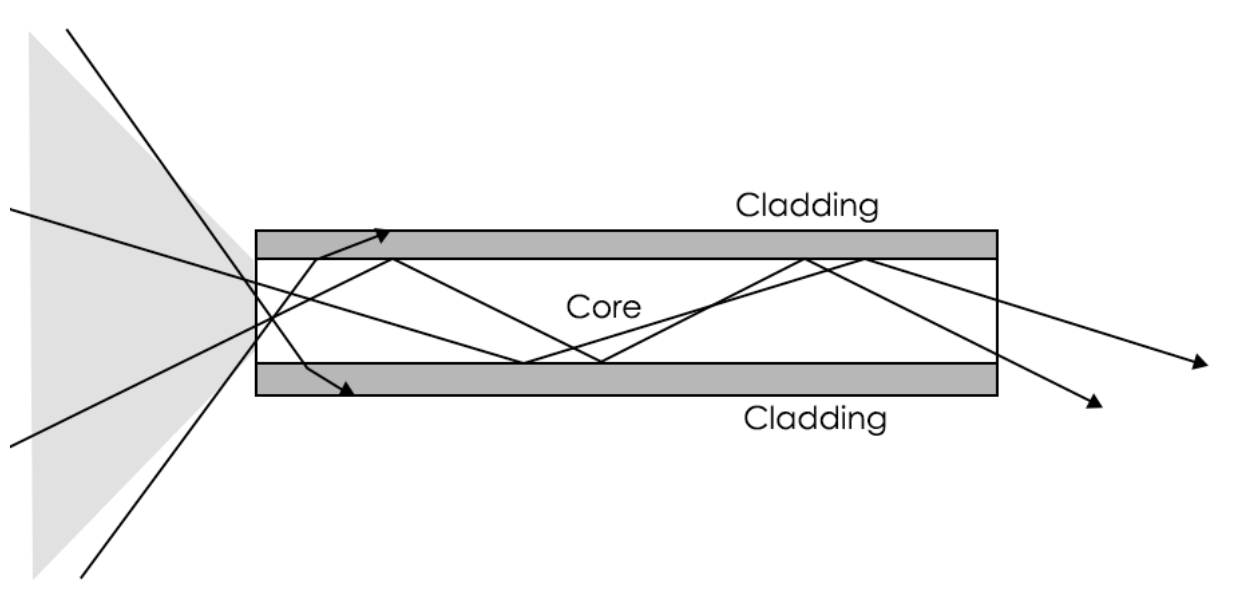
This effect guides the light along the entire fiber, even over very long distances (Ling et al., 2016).
As a metaphor, we can imagine the fiber as a tunnel of mirrors: the light is guided along the path and is able to reach the other end of the fiber.
Key points
Converting bits into signals
A computer must transmit the following sequence of bits through an electrical cable:
1 0 1 1 0 0 1
To simplify, the system uses the NRZ encoding described in these materials:
Answer the following questions:
Choosing the transmission medium
A company needs to create three different connections:
For each situation:
Why does light stay inside the fiber?
A technician must explain to a customer why a light signal can travel through an optical fiber without continuously escaping from the strand.
The cable used contains a core, cladding, coating, strength member, and outer jacket.
Answer the following questions:
To create these materials, I used generative artificial intelligence tools to support the writing process, particularly to improve the wording and style of the text, reorganize content, refine phrasing, and speed up certain editorial tasks.
Since I work independently on the production of these materials, I try to automate all activities that can reasonably be automated, so that I can devote more time to research, design, and content development.
However, artificial intelligence does not determine the content of the work: the selection of topics, structure, ideas, interpretations, examples, and teaching approach are developed by me. AI is therefore used primarily as a tool to support production and formal revision, while authorship and responsibility for the design and development of the content remain mine.
Unless otherwise stated, this material is licensed under the Creative Commons Attribution–NonCommercial–ShareAlike 4.0 International License (CC BY-NC-SA 4.0).
You are therefore free to share, redistribute, adapt, and create derivative works based on this material, provided that proper attribution is given, the material is not used for commercial purposes, and any modified or derivative versions are distributed under the same license.

Do you want to help me write articles like this one?


No responses yet